Missing Edge Resolvers

Missing Edge Resolvers (MERs), have access to additional resources to aid them in editing and resolving missing edge linestrings. These resources are located in the Options and Connectivity panels.
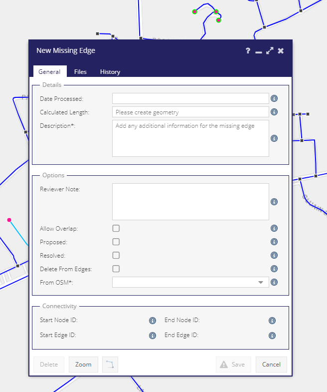
../../../../_images/MissingeEdgeFormMER.png

Options

Allow Overlap

When checked, users can save overlapping edges. This is to allow for the digitising of real-world features like underpasses and overpasses.

Resolved

When checked, these records are deemed finalised and will be imported to network edges on the next scheduled import.

Proposed

Users can mark a missing edges as Proposed. Proposed missing edges cannot also be resolved.

Delete From Edges

When checked, on the next scheduled import, for previously imported missing edges, the system will attempt to delete the record from network edges. If the edge record has any data associated with it (Segment, Project etc.) it will not be deleted. If no data is associated with it, the it will be removed from network edges and available for resolving in missing edges.

From OSM

Due to copy-write concerns it is imperative that we keep track of missing edges which have been traced in from the OSM layers. To this end, users are forced to select if the missing egde is sourced from OSM or not.

Note

As of PMS 6.1, the import of resolved missing edges to, and the deletion from, network edges, occurs at 2 am every Friday morning.

Adding/Editing Missing Roads

Layers & Grids

There are a number of layers which are in place specifically to facilitate the digitising of missing edges:

Edges (Combined)

In order for users to snap between edge features in the Network Edges dataset and features in the Missing Edges dataset, both need to sit in the same vector layer. All active network edges are included but only non-processed missing edges are included.
Due to load times for features rendered as vectors, the layer only becomes visible at scales above 1:200,000.
This layer has two thematics:
Combined: Missing Edges are styled on their Resolved status and Network Edges are styled based on their In Charge status and, if In Charge, their public/non-public status.
../../../../_images/CombinedEdges_combinededges.png
Connectivity: Network Edges are ‘Connected’, Missing Edges are either:
  1. Connected (Dyn. Node): Imported and connected to a node.

  2. Imported and connected to a network edge along its length.

  3. Imported and floating (not connected to a node nor an edge).

  4. Not imported.

../../../../_images/CombinedEdges_edgesdynamicconnectivity.png
The grid can be filtered to show only network or only missing edges using the source column.

Nodes (Combined)

In order for users to snap between edge features in the Network Nodes dataset and features in the Missing Nodes dataset, both need to sit in the same vector layer.
Three style renderings are available:
Node:
../../../../_images/CombinedNodes_defaultnodes1.png
Node Source: Distinction between a PRIME2 node and a node created by a Missing Edge or a Public/Private Split.
../../../../_images/CombinedNodes_nodesources.png
Node Connectivity
../../../../_images/CombinedNodes_dynamiccombinednodeconnectivity.png
  • Connected : Standard network edge to network edge connection.

  • Connected With Dynamic : Mix of network edge to network edge and network edge to user entered edge (or vice versa).

  • Connected User Edge : User entered edge is connected to a network edge along the length of the network edge.

  • Connected User Node : User entered edge is connected to another user entered edge.

  • Floating: Unregistered : Node connecting a user entered edge which has not yet been registered as a segment.

  • Floating : Node from a registered edge that is not connected to anything else.

  • Floating: Unimported : Node from an unimported edge that is not connected to anything else.

  • Connected: Unimported : Node from an unimported edge and is connected to another edge.
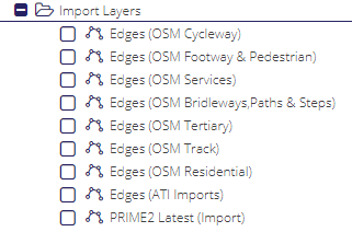
Import Layers

The Import Layers folder contains a number of vector layers which can be traced as missing edges using the Missing Edges module.
../../../../_images/ImportLayersInTree.png

Digitising Techniques

Drawing

When resolving missing edges, in order to ensure the correct snapping, it is essential to have both the Edges (Combined) & Nodes (Combined) layers turned on . Digitising without them turned on can produce snapping errors on saving the Missing Edges form.

To start drawing select the line tool from the bottom of the form and click (single) on the map. This will create the start point (displayed as a green triangle), move the mouse and single click again to create a vertex. To stop drawing, either double click the mouse or hit the escape button on your keyboard. The line end point is displayed as an orange square.
../../../../_images/Drawing1.gif

Reshaping

To reshape a drawn edge, select the drawing tool, snap the cursor to the line, and press Ctrl. A yellow square with a black outline will appear, drag the mouse to reshape the line and add a vertex.

../../../../_images/Reshaping1.gif

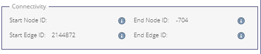
Snapping & Connectivity

Users can snap to both edges and nodes. When you are snapped to an edge or vertex the cursor point appears as an X. When snapped to a node it appears as a +.

../../../../_images/Snapping1.gif
The Connectivity panel display lets users know what their missing edge is connected to.
If Start Node Id and/or End Node Id are displaying values, then you are snapped to a node. If Start Edge Id and/or End Edge Id are displaying values, then you are snapped to an edge.
If the value displayed are negative, then you are connected to a Missing Node/Edge. If positive, then you are connected to a Network node/edge.
In this image the missing edge starts snapped to a network edge and ends snapped to a missing node. Note that if an edge starts or end connected to nothing, then the start/end Node Id will be empty until the form is saved and node is created in the database.
../../../../_images/ME_ConnectivityPanel.PNG

Tracing

Tracing is automatically enabled when digitising and the any of the layers sitting in the Import Layers folder are turned on.

To trace: - Turn on one or more of the Import Layers - Open a missing edges form - Select the line tool - Snap to a traceable layer - Start moving the mouse cursor along the line - Note that it will always try to find the shortest path. This produces the flipping effect you can see in the gif below. To countercat this, simply create a vertex before it flips and continue from that point. - If you come off the traceable layer, drawing can continue as normal. - Double click or hit Ctrl to finish drawing - Select Yes from the From OSM dropdown - Save

../../../../_images/Tracing1.gif

Splitting

Missing edges can be split into two by using the Split Missing Edge tool. This is a stand alone tool. It can be found under the Missing Edges section of the Road Schedule menu.


../../../../_images/ME_SplittingTool_Menu.PNG

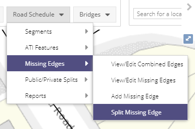
Missing edges can only be split from the Edges (Combined) layer. To split a missing edge: - Open the tool - Select the scissors icon - Snap at the desired point along the length of a line and click - Save the split

After saving the split a node will be created at the split point. Where you had one record in the grid previously, you will now have two.
../../../../_images/splitting1.gif

Deleting Missing Roads

If a Missing Road has not yet been processed, the record can be deleted by simply clicking the Delete button in that roads form.

If the Missing Road has already been processed, it is a part of the network and may have data associated with it. Clicking the Delete Road button will display the following message:

../../../../_images/RS_Missing_Roads_Delete_Message.png

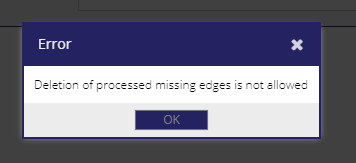
The deletion of the road has to be handled by the back-end process. To help find which roads should be deleted the Description field should be updated with the reason to delete the road (e.g. it no longer exists, it was added in error). To help find these roads it would be useful if the description also contained a keyword - it is suggested TODELETE is included to quickly find these.